// Technology
Four
technologies.
Two form the impoundment front. Two generate. Each is selected to take a structure out of the scope of a small hydropower plant (SHP), rather than to make an existing structure cheaper.
Overflow weirs in precast or cast-in-place concrete
80% of the work is done in the factory. The weir is the impoundment front and the spillway at the same time, so the conventional sectional spillway and its gates come out of the scope entirely.
Advantages
- +No spillway structure required.
- +80% of the work is done in the factory when the precast sections are made, and only 20% on site — foundation preparation and grouting of joints.
- +Factory production lowers cost and improves the reliability and durability of the elements.
Limitations
- –Large reinforced‑concrete elements have to be transported.
- –Head limited to 5 metres — above that, it is cheaper to build in place.
Section manufacture in the factory; on‑site work is foundation preparation and the grouting of joints.
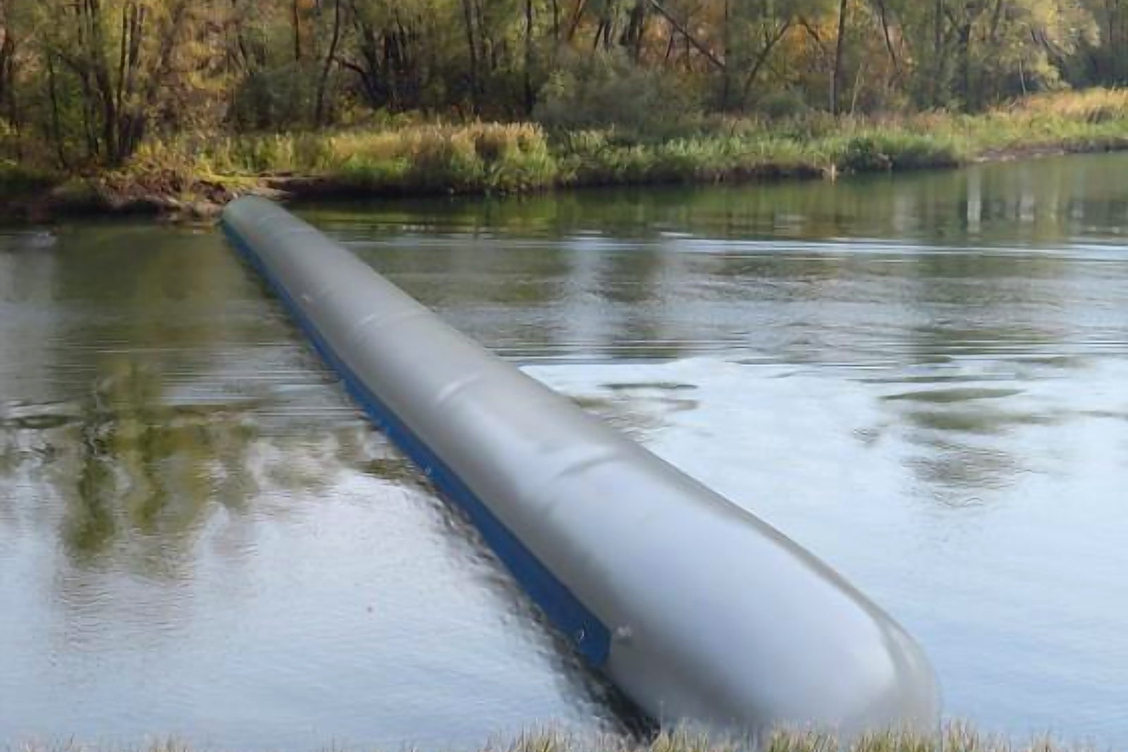 Water-filled dam on a watercourse
Water-filled dams
The height limit is the specification that decides this one: 4.5 m from Russian manufacture, 10 m from German. In exchange, the impoundment front goes up without heavy foundation work.
Advantages
- +Rapid deployment, minimal construction time.
- +Minimal construction cost for foundation preparation.
Limitations
- –Size limited: 4.5 m — Russian manufacture, 10 m — German manufacture.
- –Not a vandal‑resistant technology.
- –Relatively high cost of the material.
Suited to cases where time matters: the impoundment front is deployed without heavy foundation work.
In-stream, bulb and vortex turbines
No dam and no powerhouse — at an efficiency of 40% to 95%, depending on watercourse parameters. The width of that band is the reason a site survey comes before a capacity figure.
The band is the specification, not a range of estimates: the low end is as real as the high end until the watercourse has been surveyed.
Advantages
- +Allow construction without a powerhouse.
- +Allow construction without any dam at all.
- +Low cost of manufacture, repair and maintenance.
Limitations
- –Low output.
- –Efficiency depends heavily on watercourse parameters — from 40% to 95%.
Horizontal containerised turbines and turbines in a sealed casing
Installable in any watercourse, including existing culverts, and able to pass water over themselves. On a narrow watercourse the blocks connect in series and become the impoundment front themselves.
Advantages
- +Allow construction without a powerhouse.
- +Allow construction without any dam — using a diversion or bypass channel.
- +Low cost of repair and maintenance.
- ++Can be installed in any watercourse, and even in existing culverts; able to pass water over themselves.
++ marks the decisive advantage
Limitations
- –Efficiency depends heavily on watercourse parameters — from 40% to 95%.
- –High manufacturing cost for turbines in a sealed casing.
Total: 60–100% of a conventional scheme
Read the last column as the effect on project cost: “+” means the cost goes up, “−” means it comes down. Two values on one row mean the effect can go either way, depending on the site.
| Structure | Conventional method | Proposed concept | Δ cost |
|---|---|---|---|
| Impoundment front | Embankment dam, concrete dam | Modular overflow weir |
+10%/−10%
|
| Spillway structure | Sectional spillway of conventional profile with hydromechanical equipment | Modular overflow weir |
−10%
|
| Powerhouse | Turbine-generator block with a building and erection bays | Turbine-generator block without a building, passing floods over itself |
−20%
|
| Hydromechanical equipment | Flat service gates, bulkhead gates or radial gates | Not required |
−10%
|
| Generating equipment | Vertical or horizontal unit with an oil pressure unit and auxiliary systems (air, oil, water, fire protection) | Complete turbine-generator block requiring no additional systems — containerised or in a sealed casing |
+20%/−20%
|
| Fish passage facilities | Can reach 50% of total project cost; fish protection screens are also required at the intake | Can reach 50% of total project cost |
+50%
Same share either way — it does not go away
|
| Total | 100% | 60–100% (depending on conditions) | — |
Send a site, get an assessment
The company is ready to discuss the parameters of a specific site and watercourse. A detailed proposal needs three things: the list of sites and their locations, the hydrological data — flows and levels of the watercourse — and the target capacity with its consumption profile.